1. What is an Alarm Valve?
An Alarm Valve, also known as an Alarm Check Valve, is a critical component in a wet-pipe fire sprinkler system. It operates as a check valve by using a clapper mechanism to trap pressurized water above it, preventing reverse flow, and enabling the activation of alarms when water begins to flow into the sprinkler system during fire conditions.
In normal standby mode, the system remains pressurized, and the valve is closed. When a sprinkler is triggered, water flows past the clapper, opening the valve and simultaneously actuating mechanical or electrical alarms to signal the emergency.
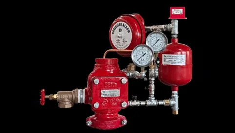
2. Structure of Fire Alarm Valve (Model H)
Model H from HD Fire Protect is a high-quality clapper check valve, featuring a grooved seat design to ensure positive water flow needed for reliable alarm operation.
Construction highlights include:
- Body material: Ductile iron manufactured to ASTM-A536, ensuring superior strength and corrosion resistance.
- Finish: Both internal and external surfaces are coated with fusion-bonded epoxy, enhancing durability.
- Connection types: Available in Flange-to-Flange, Groove-to-Groove, and Flange-to-Groove configurations, suited for varied installation needs.
- Operating pressure: Rated up to 17.5 bar (250 psi).
- Alarm trim options: Offers both constant-pressure trim and variable-pressure trim with retard chamber and can be paired with a water motor gong for mechanical alarm signaling.
3. Principle of Operation
The valve’s operation revolves around maintaining proper standby pressure and triggering an alarm during a fire:
- Standby mode: Water supply fills the system until pressures equalize; the clapper remains closed due to a bypass line.
- Activation: When one or more sprinklers discharge water, the pressure differential opens the clapper, allowing continuous water flow into the sprinkler network and simultaneously triggering mechanical and/or electrical alarms.
- Preventing false alarms: The external bypass and optional retard chamber help prevent false alarms caused by supply pressure surges or fluctuations—particularly in variable-pressure systems.
4. Specifications of Alarm Valve (Model H)
Based on HD Fire’s technical documentation, key specifications include:
- Sizes (Nominal Bore): DN 80, 100, 150, 200; also seen as NB80, 100, 150, 200.
- Material: Ductile iron (ASTM-A536); fusion bond epoxy-coated.
- Pressure rating: Up to 17.5 bar (250 psi).
- Trims: Constant pressure trim, variable pressure trim with retard chamber, water motor alarm (gong).
- Configurations: Flanged x Flanged, Grooved x Grooved, Flanged x Grooved
- Standards: UL Listed, FM Approved.
5. Classification of Fire Alarm Valves
I. By Function
- Constant-pressure trim: Designed to work with steady water supply, without requiring mechanisms to buffer pressure changes.
- Variable-pressure trim with retard chamber: Ideal for systems with fluctuating supply pressure. The retard chamber absorbs transient spikes, preventing false alarms while allowing alarms to sound during sustained flow.
II. By Installation Style
- Wet pipe systems (most common): Valve installed upright on water-filled piping; water flows instantly on activation.
- Orientation flexibility: HD Fire Model H can be installed in both vertical and horizontal orientations depending on system layout.
- Connection types (Flanged/Grooved): Selected based on piping design preferences and installation needs.
6. Advantages of Fire Alarm Valve
- Reliable alarm activation: Designed to open and sustain water flow, ensuring effective notification during emergencies.
- False alarm prevention: Bypass lines and retard chamber reduce erroneous triggering from pressure surges.
- Robust durability: Ductile iron body and epoxy coating offer strength and corrosion resistance.
- Compliance and safety: UL Listed and FM Approved, providing trusted performance.
7. Application of Fire Alarm Valve
- High-rise buildings
- Commercial complexes, malls, offices
- Hotels, hospitals, theaters
- Industrial and warehouse facilities
8. How to Install a Fire Alarm Valve?
Installation must adhere to NFPA standards and manufacturer guidelines. Key steps for Model H include:
- Install in a wet pipe sprinkler riser – upright or horizontal as required.
- Connect to correct piping using flanged or grooved fittings as specified.
- Fit trim assembly (constant or variable pressure) including gauges, test valves, drains, retard chamber, and water motor gong as needed.
- Ensure alarm control valve stays normally open and alarm test valve remains normally closed unless testing.
- Connect pressure switch to initiate electric alarms when flow is detected.
- Commission per NFPA: test periodic alarm function, confirm no leaks, clean strainer, and retard chamber.
9. Notes When Installing and Using Fire Alarm Valve
- Always install per NFPA or local fire safety codes.
- Strainers must be installed and maintained to prevent clogging clean regularly.
- Keep alarm control valve open for functionality; test valve closed except during testing periods.
- Use retard chamber in variable-pressure systems to avoid false alarms.
- Conduct regular inspections and maintenance: check for corrosion, debris, functional alarms, and adherence to installation guidelines.
- Understand warranty terms from HD Fire for two years; improper installation, misuse, or unauthorized repairs may void warranty.
Summary Table
| Section | Key Highlights |
|---|---|
| What is an Alarm Valve? | Clapper check valve that triggers alarms upon sprinkler activation |
| Structure | Ductile iron, double-seated clapper, epoxy-coated, multiple connection types |
| Operation | Standby pressurized; water flow opens clapper; alarms activated; bypass/retard prevents false triggers |
| Specifications | DN80–DN200; 17.5 bar; trims available; UL/FM approved |
| Classification | By function: constant vs. variable-pressure trim; installation: orientation, connection style |
| Advantages | Advantages Reliable, durable, flexible installation, false-alarm prevention, standard-compliant |
| Applications | Versatile use in commercial, industrial, high-rise structures |
| Installation Guidelines | It is recommended to carry out installation of alarm valves in accordance with the authorities having jurisdiction and the requirements of NFPA 13 for sprinkler system installation, with reference to NFPA 25 for inspection and maintenance considerations, and NFPA 72 for integration with fire alarm and signaling systems where applicable. |
| Notes for Use | Regular maintenance, strainers, proper valve positions, factor in warranty terms |
HD Fire Alarm Valve Model H delivers trusted performance, durability, and regulatory compliance. Carefully selected trims and meticulous installation, coupled with regular maintenance, are essential to ensuring fire systems respond swiftly and accurately ultimately safeguarding lives and property.